
Zero crossing detection with PIC16F877A
Zero crossing detection is very important, especially in power control circuits employing thyristors.
I have come across many people struggling with zero crossing detection with PIC microcontroller and thus they cannot fire triacs or SCRs as required.
So, here I have explained a simple method of detecting zero crossing with PIC16F877A, employing only two or three resistors, a bridge rectifier and an optocoupler for the hardware portion of zero cross detection.
The PIC 16F877A detects the zero crossing using the RB0/INT external interrupt function. I have explained how the zero cross is detected and how the PIC acts upon detection, below.
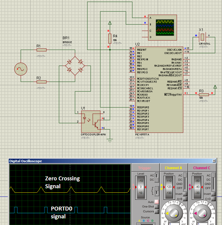
Fig. 1 - Schematic, zero crossing signal and RD0 signals
---------------------------------------------------------------------------------------------------------
Here is the code for PIC16F877A:
(You can download the source file from
https://rapidshare.com/files/604474700/ZeroCrossing.c )
---------------------------------------------------------------------------------------------------------
//Programmer: Syed Tahmid Mahbub
//Compiler: mikroC PRO for PIC v4.60
//Target PIC: PIC16F877A
//Program for zero-cross detection
//---------------------------------------------------------------------------------------------------------
unsigned char FlagReg;
sbit ZC at FlagReg.B0;
void interrupt(){
if (INTCON.INTF){ //INTF flag raised, so external interrupt occured
ZC = 1;
INTCON.INTF = 0;
}
}
void main() {
PORTB = 0;
TRISB = 0x01; //RB0 input for interrupt
PORTD = 0;
TRISD = 0; //PORTD all output
OPTION_REG.INTEDG = 0; //interrupt on falling edge
INTCON.INTF = 0; //clear interrupt flag
INTCON.INTE = 1; //enable external interrupt
INTCON.GIE = 1; //enable global interrupt
while (1){
if (ZC){ //zero crossing occurred
PORTD.B0 = 1; //Send a 1ms pulse
delay_ms(1);
PORTD.B0 = 0;
ZC = 0;
}
}
}
---------------------------------------------------------------------------------------------------------
Explanation:
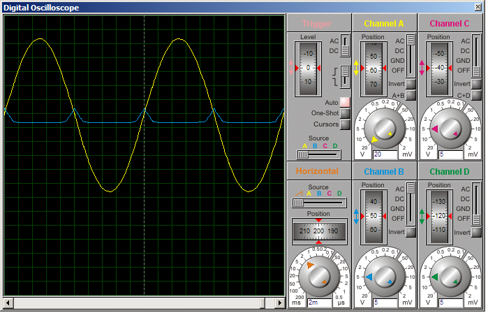
Fig. 2
Yellow - AC signal
Blue - signal on RB0
In yellow (in Figure 2), you can see the input AC voltage (sinusoidal waveform). BR1 rectifies this AC voltage to DC, but since there is no bulk smoothing capacitor, the output is not pure DC, but pulsating DC as shown below.

Fig. 3- The rectified pulsating DC
The output of the bridge rectifier BR1 is DC and current through optocoupler is limited by resistors R1 and R2 (you may use a single resistor instead of 2 if you want, but using 2 resistors distributes the power dissipation and thus generates less heat and lower power per resistor).
So, the optocoupler LED stays on for most of the cycle except when the AC sine wave "crosses zero" (is around zero). While the optocoupler LED is on, the transistor is on and so pulls pin RB0 of PIC16F877A low.
PIC16F877A is coded to enable the external interrupt. An interrupt is generated upon the falling edge of RB0. The diagram below will illustrate what I mean by falling edge.

Yellow - signal on RB0
Blue - signal from RD0
During most of the cycle, the optocoupler LED is on and so RB0 is low. When the optocoupler LED is off as the AC wave is about to cross "zero", RB0 goes high. The transition from low to high on RB0 is a rising edge. When the optocoupler LED is then again turned on as the AC wave crossed the "zero" level (zero crossing), RB0 goes low. This transition from high to low is a falling edge. And upon a falling edge, an interrupt is generated.
When an interrupt is generated, the ZC flag is set (see code above). In the main code, ZC flag is always checked (this is called polling a flag). When ZC flag is set (zero crossing occurred), a 1ms pulse is generated on RD0 (PORTD0) and then the ZC flag is cleared. For example's sake, I have produced a 1ms pulse. You can do whatever you want upon zero-cross detection. The ZC flag is then again continuously polled to check for next interrupt.
You can see all this illustrated in Figures 2, 3 and 4 above.


